Thermistor
The term thermistor refers to a "thermal resistor". It is basically a resistor that changes due to the surrounding temperatures. There are two types of thermistor. NTC (Negative Temperature Coefficient) and PTC (Positive Temperature Coefficient) types. NTC type thermistors will gain resistance as the temperature drops, as PTC types will gain resistance as the temperature rises.
The thermistor i was to test was an NTC type, which means the resistance should start to drop once i apply heat to it. I hooked it up to a power supply and a multimeter, and placed it in a container of water. I then applied heat in the form of a stove element, and used a thermometer to track temperature as i recorded my results.
Water temp Resistance
33°c 1.36K ohm
35°c 1.33K ohm
40°c 1.14K ohm
45°c 0.96K ohm
50°c 780 ohm
55°c 680 ohm
70°c 407 ohm
75°c 390 ohm
The results above show a steady decrease in resistance as the temperature rises. It is within specification and is good for continued use.
Thermo Fan Switch
A thermo fan switch is very similiar to a thermistor, in that it is affected by temperature, yet instead of gradually changing with the temperature, it is set to switch at a pre-determined temp.
In testing the switch, we must measure the resistance across it, and determine the temperature it will switch at while applying heat to it.
Temperature Resistance
Room Temp 70.5 ohm
45°c 0.8 ohm
50°c 0.7ohm
55°c 0.9ohm
This particular thermo switch is far beyond spec, as it is switching at only 45°c. The specification for this fan is 80°c. So it is unserviceable and must be replaced.
Tuesday, 5 July 2011
Monday, 4 July 2011
MAF/MAP Sensors
MAP (Manifold Absolute Pressure) and MAF (Mass Air Flow) Sensors measure the load on an engine, and are directly connected to the amount of fuel the injectors will spray into the engine. If these are faulty it will affect the fuel/air mixture of the engine and can cause serious loss of power/efficiency, and even cause damage to the engine. Other factors, such as vacuum leaks etc. can also cause faults with the measured load of the engine.
My first task was to wire up a MAP sensor and perform a bench test against manufacture specifications. There are three pin-outs, a 5v reference, an earth wire, and a signal output to the ECU.
Vane Angle Voltage Out
0° 2.2v
20° 4.7v
40° 6.8v
60° 7.6v
80° 8.1v
100° 8.5v
120° 9.4v
My first task was to wire up a MAP sensor and perform a bench test against manufacture specifications. There are three pin-outs, a 5v reference, an earth wire, and a signal output to the ECU.
After connecting the MAP sensor to a power supply (5v) and my multimeter, i used a Mityvac to apply negative pressure to it, and recorded my outcome. The readings i got adhered to the spec standards of the MAP sensor. This means that the sensor is serviceable and can continue to be used on the vehicle.
There are two variants of MAF sensors. Vane Types, and Hot-Wire Types. The picture below is of a Hot-Wire Type. This type uses a voltage divider circuit containing an electrically heated element (Made of a PTC thermistor) to measure the air flow through its casing.
Unfortunately there were no Hot-Wire Type MAF sensors available to us, so we were unable to perform a bench test on one.
The Vane-Type MAF uses an L shaped plate with a contact, and a resistor much like that of the TPS, to operate. Incoming air forces the plate open, and the contact moves across the resistor, changing the output signal. This type is quite restrictive, as the incoming air must literally force its way through the MAF, reducing flow and effiiciency. It is not used in many modern cars, and has been replaced with the much more efficient Hot-Wire MAF's, and MAP sensors. Below is a picture of a Vane-Type MAF
We wired up a MAF and took readings from our multimeter
at different open positions:
Vane Angle Voltage Out
0° 2.2v
20° 4.7v
40° 6.8v
60° 7.6v
80° 8.1v
100° 8.5v
120° 9.4v
Throttle Position Sensor (TPS)
The two types of TPS are the Switching Type, and the Potentiometer Type. The Switching Type has a switch at either peak of the throttles turning circle. As the contact connects with either of these points, it will switch either the WOT (wide open throttle) or Idle circuits. Anywhere in between it will continue normal driving patterns. The Switching Type TPS is quite an early model of TPS, only allowing the ECU to adjust ignition timing under WOT and to activate injector cut-off at idle.
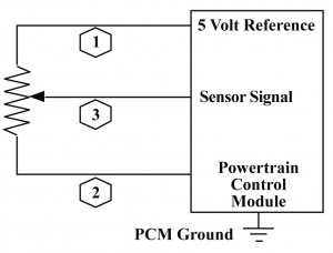
The more modern and also more common style of TPS, the Potentiometer type, has a contact connected to the throttle butterfly, and a set resistor. The contact moves as the butterfly is opened, and is moved across the resistor. The "Rule of thumb" specifications, if run on a 5v reference, are 0.45-0.5v at idle, and approx. 4.5v at WOT. Below is a simple diagram of the inner functions of a potentiometer-type TPS.
To test, I set my multimeter to DC Volts scale, and open the throttle with my hand. My findings were as follows:
Throttle angle Voltage output
0° 0.396v
25° 1.451v
50° 1.68v
75° 3.9v
85° 4.1v
90° 4.28v
Below is a graph explaining these findings
The more modern and also more common style of TPS, the Potentiometer type, has a contact connected to the throttle butterfly, and a set resistor. The contact moves as the butterfly is opened, and is moved across the resistor. The "Rule of thumb" specifications, if run on a 5v reference, are 0.45-0.5v at idle, and approx. 4.5v at WOT. Below is a simple diagram of the inner functions of a potentiometer-type TPS.
In order to bench test a TPS, we must wire up a 5v supply and earth to two of the pinouts, and connect a multimeter to the output pin. Before we do this, we must ofcourse find the pinout diagram for the TPS. This i found by google searching the part number.
Throttle angle Voltage output
0° 0.396v
25° 1.451v
50° 1.68v
75° 3.9v
85° 4.1v
90° 4.28v
Below is a graph explaining these findings
Wednesday, 22 June 2011
Wiring up Ignition Systems
My first task was to wire a simple ignition circuit consisting of a coil, spark plug, power supply, and a function generator to trigger the spark.
The next circuit to build used a distributor to send a signal to the ignition module. The circuit was wired up alot like the last, but with a distributor in place of the function generator. Spinning the distributor rotor creates a signal much like that of the function generator, causing the spark to fire as each tooth of the rotor passes the pick up.
This circuit did not require an ignitor as the coil incorporated an ignitor inside of it. This meant that i wired it straight to the function generator to complete the circuit. Once wired up, i tested it's operation and it seemed to work well.
A simple enough circuit, the hardest part was adjusting the function generator to operate the coil correctly, as it was the first time I had used one. I also had a slight fault in my dwell time pattern, which I could not fully remove, even after replacing a few of the components
The next circuit I built used an ignition module to amplify a trigger signal to the coil. This circuit is alot like the last one I built, except the trigger is amplified by an ignition module, which means a much smaller signal is needed to ignite the spark. To wire this, I first had to find out the pin outs for the ignition module I was using, this particular one being from a Toyota 4a-fe engine. After some research on the always faithful Google, I found a pin out diagram, and also found the reason for the mysterious fifth pin (I already knew the use for the four others, just not which went where). The last pin was for a misfire detection function.
The four pins used on the ignition module consisted of Power Supply +12v, Earth, Trigger signal, and Output to Coil.
Other than figuring out the wiring of the ignition module, this circuit was quite simple to wire up, as it was very similar to the last, and the function generator was already calibrated.
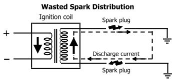
The next circuit to build used a distributor to send a signal to the ignition module. The circuit was wired up alot like the last, but with a distributor in place of the function generator. Spinning the distributor rotor creates a signal much like that of the function generator, causing the spark to fire as each tooth of the rotor passes the pick up. The third circuit I built was for a wasted spark ignition system. For this circuit, I used the function generator, and the same ignition module, but instead of the single plug coil, I used a wasted spark coil pack, with two leads and spark plugs. The wiring was much the same as the other circuits, except for the fact that there were two seperate spark plugs firing off the one coil. This is achieved by grounding one of the spark plugs through the other plug, and then back into the coil, to create a full circuit. The property of electricity that it naturally wants to return to its source, makes this possible.
Below is a simple diagram showing the internal functions of a wasted spark coil for a 6 cylinder vehicle.
On this coil, there is one 12v supply pin, but in others there may be one for each coil. It shows how two cylinders are triggered at the same time, and subsequently fire at the same time also. This is the reason for the name 'Wasted Spark', as one spark is always fired on the exhaust stroke.
The next circuit I built contained a Coil Over Plug setup, which contains a coil and built-in ignitor in one unit (see below), removing the need for a seperate ignitor. These units will run one coil for each cylinder, making them very efficient, and less likely to fail. A bad point is that the are difficult to test, as there is no access to the coil primary.
Wednesday, 8 June 2011
Testing Ignition Coils
First task we had was to obtain two different ignition coils, and test them against specification. We hadto determine the part numbers, and search the spec sheets on google. Once that was completed, we set to testing.
My two coils were:
C6R-500
&
CTI-118
My test results were as follows:
C6R-500
Operating Voltage: 12v
Primary Resistance Specification: 1.20 - 1.50 ohms
Actual Primary Resistance: 1.3ohms
Secondary Resistance Specification: 6.5K - 8.5K ohms
Actual Secondary Resistance: 8K ohms
Earth leakage: OL
CTI-118
Operating Voltage: 12v
Primary Resistance Specification: 1.0 - 1.3 ohms
Actual Primary Resistance: 1.2ohms
Secondary Resistance Specification: 8.5K - 9.5K ohms
Actual Secondary Resistance: 9.33K ohms
Earth Leakage: OL
Both coils were in good condition and 100% serviceable.
If resistances were above specification, this may be caused by a break in the windings, and could result in incorrect charging and misfire.
If they were below specification, it may cause over heating and damge to other components.
My next task was to test a wasted spark coil.
I used a 6 output Coil from a Series 1 Holden Commodore 3.8l V6 89-90.
Part No: TIC032
I tested each of the three coils separately.
My results were as follows:
Coil 1 Primary: 1.2ohms
Coil 2 Primary: 1.2ohms
Coil 3 Primary: 1.1ohms
Coil 1 Secondary: 12.67K ohms
Coil 2 Secondary: 12.73K ohms
Coil 3 Secondary: 12.75K ohms
My two coils were:
C6R-500
&
CTI-118
My test results were as follows:
C6R-500
Operating Voltage: 12v
Primary Resistance Specification: 1.20 - 1.50 ohms
Actual Primary Resistance: 1.3ohms
Secondary Resistance Specification: 6.5K - 8.5K ohms
Actual Secondary Resistance: 8K ohms
Earth leakage: OL
CTI-118
Operating Voltage: 12v
Primary Resistance Specification: 1.0 - 1.3 ohms
Actual Primary Resistance: 1.2ohms
Secondary Resistance Specification: 8.5K - 9.5K ohms
Actual Secondary Resistance: 9.33K ohms
Earth Leakage: OL
Both coils were in good condition and 100% serviceable.
If resistances were above specification, this may be caused by a break in the windings, and could result in incorrect charging and misfire.
If they were below specification, it may cause over heating and damge to other components.
My next task was to test a wasted spark coil.
I used a 6 output Coil from a Series 1 Holden Commodore 3.8l V6 89-90.
Part No: TIC032
My results were as follows:
Coil 1 Primary: 1.2ohms
Coil 2 Primary: 1.2ohms
Coil 3 Primary: 1.1ohms
Coil 1 Secondary: 12.67K ohms
Coil 2 Secondary: 12.73K ohms
Coil 3 Secondary: 12.75K ohms
This coil pack was completely serviceable, as all of my reading came within, or near specification.
If either resistance was low, especially the secondary, it could mean there is a short circuit in the windings, and the coil will not operate correctly, if at all. If resistance was high, for example, OL, this could mean there is an open circuit in the windings, and the coil will not operate at all.
The next test was on Ballast resistors. I used two different Ballast resistors for my test.
Part No. BR1 and Part No. BR3.
I had to obtain the resistance specification for each. These I found on a specification sheet stored with the resistors.
Specs were:
BR1 = .9 - 1.1ohm
BR3 = 1.5 - 1.7ohm
My readings were:
BR1 = .7ohm
BR3 = 2ohm
Neither of these Ballast resistors were serviceable, as each was outside of their proper specification. Lower resistance may cause overheating of the coil and damage to the ignition components, while higher resistance may cause improper charging of coil and may lead to misfire, especially at higher RPM's
Monday, 6 June 2011
Injector testing
This section includes injector testing, and also injector cleaning.
First up, we did electrical testing. We found four injectors, and tested their resistance according to the specification of each. We also tested earth leakage to the shell of the injector. Before this was done though, we hadto check the internal resistance of the multimeter used, and then subtract that from our total reading. On each of my four injectors, my resistance readings were within spec, and none of them had any earth leakage.
My readings were as follows:
Injector 1: 13.9
Spec: 13.9
Earth Leakage: OL
Injector 2: 13.9
Spec: 13.8
Earth Leakage: OL
Injector 3: 13.8
Spec: 13.8
Earth Leakage: OL
Injector 4: 13.9
Spec: 13.8
Earth Leakage: OL
If these readings were not within specification, they may cause incorrect opening/closing, or may cause them not to operate at all.
After these were completed i began bench testing the injectors on specialist equipment used for testing/cleaning injectors.
I tested leakage and flow on each of my four injectors. For flow, i hadto test over 15 seconds, and then multiply that figure by four to get my reading. I hadto do this as if i had simply run the test over a minute, the test tube would have overflowed.
My readings are as follows:
Injector 1: Flow = 190cc
Leakage = 0DPM (Drips Per Minute)
Injector 2: Flow = 190cc
Leakage = 0DPM
Injector 3: Flow = 190cc
Leakage = 0DPM
Injector 4: Flow = 190cc
Leakage = 0DPM
On the earth leakage test, pressure is held behind injectors with them closed, and leakage is observed and determined over a minute.
If flow is below specification, the injector may cause its cylinder to run lean, and cause a lack of performance/fuel economy. If leakage is present, it will cause unwanted drips while engine is inactive, and cause fuel build-ups in the runners of the engine.
First up, we did electrical testing. We found four injectors, and tested their resistance according to the specification of each. We also tested earth leakage to the shell of the injector. Before this was done though, we hadto check the internal resistance of the multimeter used, and then subtract that from our total reading. On each of my four injectors, my resistance readings were within spec, and none of them had any earth leakage.
My readings were as follows:
Injector 1: 13.9
Spec: 13.9
Earth Leakage: OL
Injector 2: 13.9
Spec: 13.8
Earth Leakage: OL
Injector 3: 13.8
Spec: 13.8
Earth Leakage: OL
Injector 4: 13.9
Spec: 13.8
Earth Leakage: OL
If these readings were not within specification, they may cause incorrect opening/closing, or may cause them not to operate at all.
After these were completed i began bench testing the injectors on specialist equipment used for testing/cleaning injectors.
I tested leakage and flow on each of my four injectors. For flow, i hadto test over 15 seconds, and then multiply that figure by four to get my reading. I hadto do this as if i had simply run the test over a minute, the test tube would have overflowed.
My readings are as follows:
Injector 1: Flow = 190cc
Leakage = 0DPM (Drips Per Minute)
Injector 2: Flow = 190cc
Leakage = 0DPM
Injector 3: Flow = 190cc
Leakage = 0DPM
Injector 4: Flow = 190cc
Leakage = 0DPM
On the earth leakage test, pressure is held behind injectors with them closed, and leakage is observed and determined over a minute.
If flow is below specification, the injector may cause its cylinder to run lean, and cause a lack of performance/fuel economy. If leakage is present, it will cause unwanted drips while engine is inactive, and cause fuel build-ups in the runners of the engine.
Friday, 22 April 2011
Circuit 3
My third and final circuit to be made was to work in conjunction with a vehicles oxygen sensor, and should give readings via LED's to interpret the state of the vehicles air/fuel ratio.
To achieve the necessary outputs to engage each LED i would need a semi-complicated circuit involving a triple Op Amp chip.
Other than the chip itself, me circuit consisted of:
3 x 1K Resistors
1 x 10K Resistor
1 x 410ohm Resistor
1 x 470ohm Resistor
1 x 270ohm Resistor
1 x 9.1v Zener Diode
3 x 1N4001 Diodes
2 x 0.1 uF Capacitors
3 x 5mm LED's (Red, Yellow, Green)
This circuit was much more difficult to map out than the previous circuits, as not only was it alot more complex, but we also had a restricted amount of space to fit it into, and also the pin-outs on the chip were not always in the easiest place to tap into.
This meant that alot of trial and error on the computer screen was necessary.
Once I had completed this seemingly possible task, i set to acquiring my components and creating my circuit.
This required alot more skill than the last two, as the whole circuit was alot more compacted in design. After a couple of hiccups in the build process, the circuit seemed to come together nicely.
When i went to test it however, i found that the potentiometer setup that we have been supplied for the testing of our circuits, was faulty, and a short circuit somewhere inside the potentiometer had caused it to have a steady output of 5v, which is the input voltage it had been given in the first place. This is also far too high for our circuits to be tested on, as they are designed for fluctuations between .1v and 1v.
This meant i had no correct way to test my circuit. From what i did see though, i found i had a loose connection in one of my Op Amp pin-outs, which caused one of my LED's to flicker when touched.
Subscribe to:
Posts (Atom)