Sunday 17 July 2011

O² Sensor on Car

The O² Sensor is an integral part of fine tuning the performance, fuel efficiency, and emissions of a vehicle. It senses, and then adjusts, the fuel-air ratio to get an optimal burn, and then works in partnership with the cars Cat Converter to remove harmful emissions.

We tested the O² sensor on a Toyota 1ZZ engine. The 1ZZ has a 3-wire O² sensor. The wires represent the following: White = Heater Power, White (Black strip) = Heater Earth, Black = O² Signal Wire.


This is Zirconia switching type sensor. When the back probe was inserted we got this oscilloscope reading:
From a visual inspection of this signal pattern, we can discern that the signal fluctuates from as low as .05v, to .785v. Our Oscilloscope could not give us an average voltage, but with a quick calculation, I came up with an average of around .418v. This signal had 8 cross counts (Cross counts being one fluctuation from high to low, or visa versa).

We then warmed the engine up in order to test the 0² sensor in closed loop mode. 
In closed loop, the signal from the 0² should cycle above and below .5v. The result we recieved from the sensor was far from that.

 The signal was floating at just over .1v. This is a very undesirable signal. The cross counts were unmeasurable as there was barely any change in the signal. A sudden acceleration showed a much better resulting signal.
The highest voltage recorded on this signal was .818v. This signifies a rich mixture. This is what is desirable, as the reason we tested with a quick acceleration was to simulate a rich running condition.
Next we recorded the signal after a sudden drop in acceleration, to idle. This was to simulate a lean condition.
The signal did just as i thought it would. As you can see, it has dropped from the good, clear signal, back down to the flat, low signal that it was giving originally. 

Apart from at idle, this 0² Sensor gave good readings, leading me to believe that there is a fault in the wiring for the sensor. From the readings i have taken, I believe that this 0² sensor is functioning correctly, and that the circuit for the sensor must be checked for faults.

Scan Tool Diagnostics

For this segment we used a Hanatec Scan Tool on a Toyota 1ZZ engine.


The table below is an example of live data from a scan tool.


A Scan Tool is a highly effective tool in diagnosing problems in a vehicle, as it narrows down problems for a faster diagnosis/repair. Live data is also really helpful as it shows what is happening, as it is happening.


Type of information(PID=Parameter Identification)
Letters to describe it
Value of data
Units for data
Engine Load(how much air comes in)
AFM(MAF)
2.58
Gm/s
Engine RPM
Engine speed
700
RPM
Throttle angle
Throttle position
11
%
Engine coolant temperature
Coolant temperature
71
C
Intake air temperature
22
C
Fuel Injection opening pulse
Injector pulse width
2.7
ms
Transmission select position
shift
4

Vehicle speed
0
0
Km/h
Oxygen sensor(s)
O2 sensor B1 S1
0.890
V
Fuel Trim
Short fuel trim#1
-20.3
%
Idle control
IAC duty ratio
37.5
%
Power steering condition
PS
off

Air Conditioning condition
A/C cut signal
on

Exhaust Gas Recirculation(EGR)
-
-
-
Fuel Evap or Purge condition
EVAP VCV
OFF
-
Malfunction Indicator Light
Warning light/MIL
on
on


The diagnostic plug on this particular engine was located under the bench. If it was on a vehicle, it may be located in the dash, or in the engine bay. As this particular engine is OBDII, there are particular laws the manufacturer must follow in mounting the plug, and it will most probably be located under or near the steering wheel.


< http://en.wikipedia.org/wiki/On-board_diagnostics#OBD-II_Diagnostic_connector > This link shows information on the OBDII connector and laws surrounding it.


Next we plugged in our scan tool and asked our tutor to introduce a fault into the system. We then turned on the Scan tool and entered the required data for it to begin diagnosis. The fault code came up as PO120. After searching the workshop manual, I found the fault was coming from the TPS. The first test I did was a visual check. I checked rigidness and condition of plugs, I looked for nicks, breaks or corrosion in the wire, and checked the condition of the sensor itself. I then checked voltage supply to the sensor. My multimeter showed 0v. I then reported this to the tutor and as the fault wasn't anywhere I could repair, he switched the fault switch back on and I carried on. To clear the codes, I pressed the "clear codes" button on the Scan Tool, and turned the ignition on then off again. The Scan Tool showed no codes.


Monday 11 July 2011

Input Sensors and Actuators On Car

For this section we captured the patterns of various sensors on a Toyota 1ZZ engine, and recorded the parameters.
The first sensor i tested was an ECT sensor.
 At cold, the thermistor has the most resistance. This will cause a high output signal at the ECU (The ECU uses a voltmeter-type device to measure volt drop across the sensor, this is unlike most of the othe sensors).
 As you can see, the voltage reduces as the temperature rises. The vertical axis is voltage, and the horizontal axis is time. This is being recorded as the vehicle is started up and begun to warm up. At cold, a normal voltage for an ECT is 4-4.5V, once is is warm, you should see around .5-.9v. Anything below this and the vehicle is in danger of overheating. A bad earth on an ECT could cause a high reading, as the voltage drop will be above specification due to the added resistance. This will cause the ECU to recieve a false reading, and use alot of excess fuel. Other reasons for a fault on the ECT could be a fault in the Thermistor istelf, a bad or dirty plug connection, or bad battery voltage. If any of these faults were present, the oscilliscope pattern may look the same, but the ratio between the temperature and the voltage will be different. If there was a loose connection somewhere, you may get fluctuations in the pattern.


The next sensor I tested was a MAP sensor.
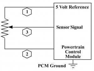
As you can see from this simplified diagram, the MAP sensor works much like any other potentiometer. The potentiometer in a MAP sensor is eqquipped with a diaphram, and connected to a source of manifold pressure. As manifold pressure rises (towards atmospheric, or over in forced induction applications), so does the output voltage. This is caused by the potentiometer moving along the resistor, creating less resistance in the circuit. See below, an oscilloscope pattern we captured by placing the engine under load.
As you can see, we gave the engine short bursts of acceleration. Under a snap acceleration, the voltage from the MAP sensor may reach 4-4.5v. At idle it will sit near .5v, and under acceleration, this will climb with load introduced to the engine. A bad earth, bad connection, etc may cause the MAP to give a false reading. If this reading is too low, it will run the engine lean, and cause a notable lack of power. This is also dangerous to the engine, as running lean can cause problems such as knocks, etc. An unservicable diaphram in a MAP sensor may cause the low manifold pressure to have no effect on the MAP, and this will cause the engine to run rich. You will also feel a lack of power in this instance, and prolonged driving will cause damage such as fouled spark plugs, fouled 0² sensor, fouled CAT converter, among other problems that rich running can cause, including emissions.

The TPS sensor was the next to be tested.
The type of TPS we tested was the more modern Pontentiometer-Type sensor. This type has a contact mounted on the shaft, and a set resistor on which it moves across. At idle, the sensor should show approx. .5v, at WOT (Wide Open Throttle), it should show approx. 4.5v, and anywhere in between while driving. Below is a oscilloscope pattern of a TPS we captured.
In the above picture, we opened the throttle half way, then to WOT, then released it. As you can see, the voltage rises to 2v, then up to around 4v as WOT was applied. Then as we realeased, it dropped back to .5v. A faulty earth or bad connection will cause a lower voltage at the sensor wire, and will cause a laggy throttle response. If the TPS had been removed, or re-adjusted in the past, this may also cause an incorrect voltage.

IAT Sensor
The IAT sensor works with the MAP sensor (Most MAF sensors have IAT's incorporated in their design) to measure the air entering the vehicles intake. At room temperature, the approx. voltage of the IAT is 2.5v, this decreases as the incoming air becomes heated. Below is an Oscilloscope reading of an IAT measuring air as the temperature increases.
The beginning of this pattern shows room temperature. As we applied heat with a heat gun, the temperature rose, and as it did, the voltage dropped to under .5v. The voltage at lower temps is higher, and it is made this way as the air is more dense, therefore richer in oxygen. Therefore, it requires more fuel in the mixture.

The 
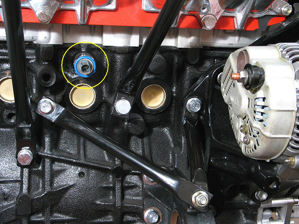
CAS (CAM ANGLE SENSOR) is my final sensor in this segment.

There are numerous types of Cam angle/Crank position sensors that come factory with different vehicles. Toyota's 4A-fe has a CAS built into it's distributor. The 1ZZ has an induction type CPS on the crank. The sensor we tested was on the 1ZZ. Below is an oscilloscope pattern for it.
We used four different functions on a multimeter to find the best one.
DC Volts: 19.5mV
AC Volts: 1.2v
Frq : 0.09kHz
% Duty Cycle: 14.1%

Thursday 7 July 2011

Fuel Pressure and Flow testing

Fuel pressure and flow is an important part of keeping the fuel/air mixture of a vehicle correct. Fuel flow is especially important with large vehicle applications, and fuel pressure is a huge factor in forced induction vehicles. If there is a fault with a fuel blockage, or your FPR or fuel pump has a fault, it can affect your vehicles performance greatly. A fuel leak may also cause low flow/pressure, or a blockage after the FPR may cause a high fuel pressure, which will cause a rich mixture and can cause damage to the fuel system.
If a fuel system has low flow or pressure, it may cause the engine to run lean, and it could have a noticeable lack of performance. Testing pressure is a huge part of diagnosing faults in the fuel system.


Testing fuel pressure on this engine (4a-fe) was simple, as the engine had a fuel pressure gauge setup on it's stand.

First, we looked at pressure at idle. The vehicle specification was 38-44psi. The gauge showed 36psi.
The next test was a fuel blockage test. We used a brakeline clamp to seal the fuel line AFTER the Fuel Pressure Regulator, and measured the pressure. It showed 89psi. Note: we only did this within a matter of a couple of seconds, this should not be done for extended periods of time.
 We then tested fuel pressure with 0 vacuum. The pressure gauge read 45psi.
We then turned the engine off and waited 5min to check the let down of the fuel system. After 5min the pressure was at 40 psi.

Tuesday 5 July 2011

Flash Codes

Determining flash codes was the first 'on-car' task we were set. We were to use a fused link wire to short two pins on the Diagnostic plug of a 4a-fe, to place the ECU in diagnostic mode. Once that was done, we counted the times that the "Check Engine" light flashed, and converted it to a suitable number. We then checked it against a specification sheet.

 Our tutor introduced three faults into our system, which we had to diagnose and then repair. The three faults, and their codes are listed below.

Code Number                         System Affected                        Condition Described
24                                            Intake Air Temp                          Effect air fuel ratio
31                                            Vacuum Sensor                           Running real bad
41                                            Throttle Position Sensor               Bad idle

 Once the codes were discovered, we first did a visual check of the faulted circuits. In all three cases, the plugs were disconnected, but if the visual check turned out fine, we would haveto continue to test.

Once the plugs were plugged back in, i turned the ignition off then on again to clear the fault codes.

O² sensor

An oxygen sensor, or lambda sensor, is an electronic device that measures the proportion of oxygen (O2) in the exhaust. It gives out a 0.1v - 1v signal depending on the oxygen levels present. If running well, it should be giving near enough to 0.5v, and switching above and below it, to aid in the removal of NOx (Oxides of Nitrogen), and CO's (Carbon Monoxide).
Unfortunately we were unable to perform our own tests on an O² sensor, but our tutor was able to give us an indepth demonstration on the workings of the sensor.

Knock Sensor

A knock sensor uses a "Piezooelectric Crystal" to turn vibrations into a voltage. If a knock is sensed on the engine, the crystal creates an A/C signal down the signal wires, which the ECU picks up. If knock is sensed, the ECU will place the engine on knock map, or "safe mode". This runs the engine rich to attempt to remove any predetonation in the combustion chamber, and remove any "hot spots". If your engine is on knock map, you will notice a reduction in power, and a rise in fuel usage.

To test the knock sensor, i had to hook the two wires up to my oscilliscope, and simulate an engine knock by gently tapping the sensor against a hard surface. What i got was a small analog signal on the oscilliscope.

Testing a thermistor & thermo fan switch

Thermistor
The term thermistor refers to a "thermal resistor". It is basically a resistor that changes due to the surrounding temperatures. There are two types of thermistor. NTC (Negative Temperature Coefficient) and PTC (Positive Temperature Coefficient) types. NTC type thermistors will gain resistance as the temperature drops, as PTC types will gain resistance as the temperature rises.

The thermistor i was to test was an NTC type, which means the resistance should start to drop once i apply heat to it. I hooked it up to a power supply and a multimeter, and placed it in a container of water. I then applied heat in the form of a stove element, and used a thermometer to track temperature as i recorded my results.

Water temp              Resistance
33°c                        1.36K ohm
35°c                        1.33K ohm
40°c                        1.14K ohm
45°c                        0.96K ohm
50°c                        780 ohm
55°c                        680 ohm
70°c                        407 ohm
75°c                        390 ohm

The results above show a steady decrease in resistance as the temperature rises. It is within specification and is good for continued use.

Thermo Fan Switch
A thermo fan switch is very similiar to a thermistor, in that it is affected by temperature, yet instead of gradually changing with the temperature, it is set to switch at a pre-determined temp.
In testing the switch, we must measure the resistance across it, and determine the temperature it will switch at while applying heat to it.

Temperature                           Resistance
Room Temp                              70.5 ohm
45°c                                          0.8 ohm
50°c                                          0.7ohm
55°c                                          0.9ohm

This particular thermo switch is far beyond spec, as it is switching at only 45°c. The specification for this fan is 80°c. So it is unserviceable and must be replaced.

Monday 4 July 2011

MAF/MAP Sensors

MAP (Manifold Absolute Pressure) and MAF (Mass Air Flow) Sensors measure the load on an engine, and are directly connected to the amount of fuel the injectors will spray into the engine. If these are faulty it will affect the fuel/air mixture of the engine and can cause serious loss of power/efficiency, and even cause damage to the engine. Other factors, such as vacuum leaks etc. can also cause faults with the measured load of the engine.

My first task was to wire up a MAP sensor and perform a bench test against manufacture specifications. There are three pin-outs, a 5v reference, an earth wire, and a signal output to the ECU.
After connecting the MAP sensor to a power supply (5v) and my multimeter, i used a Mityvac to apply negative pressure to it, and recorded my outcome. The readings i got adhered to the spec standards of the MAP sensor. This means that the sensor is serviceable and can continue to be used on the vehicle.

There are two variants of MAF sensors. Vane Types, and Hot-Wire Types. The picture below is of a Hot-Wire Type. This type uses a voltage divider circuit containing an electrically heated element (Made of a PTC thermistor) to measure the air flow through its casing. 
Unfortunately there were no Hot-Wire Type MAF sensors available to us, so we were unable to perform a bench test on one.

The Vane-Type MAF uses an L shaped plate with a contact, and a resistor much like that of the TPS, to operate. Incoming air forces the plate open, and the contact moves across the resistor, changing the output signal. This type is quite restrictive, as the incoming air must literally force its way through the MAF, reducing flow and effiiciency. It is not used in many modern cars, and has been replaced with the much more efficient Hot-Wire MAF's, and MAP sensors. Below is a picture of a Vane-Type MAF
We wired up a MAF and took readings from our multimeter 
at different open positions:

Vane Angle        Voltage Out
0°                        2.2v
20°                     4.7v
40°                     6.8v
60°                     7.6v
80°                     8.1v
100°                   8.5v
120°                   9.4v

Throttle Position Sensor (TPS)

The two types of TPS are the Switching Type, and the Potentiometer Type. The Switching Type has a switch at either peak of the throttles turning circle. As the contact connects with either of these points, it will switch either the WOT (wide open throttle) or Idle circuits. Anywhere in between it will continue normal driving patterns. The Switching Type TPS is quite an early model of TPS, only allowing the ECU to adjust ignition timing under WOT and to activate injector cut-off at idle.

The more modern and also more common style of TPS, the Potentiometer type, has a contact connected to the throttle butterfly, and a set resistor. The contact moves as the butterfly is opened, and is moved across the resistor. The "Rule of thumb" specifications, if run on a 5v reference, are 0.45-0.5v at idle, and approx. 4.5v at WOT. Below is a simple diagram of the inner functions of a potentiometer-type TPS.
 In order to bench test a TPS, we must wire up a 5v supply and earth to two of the pinouts, and connect a multimeter to the output pin. Before we do this, we must ofcourse find the pinout diagram for the TPS. This i found by google searching the part number.

To test, I set my multimeter to DC Volts scale, and open the throttle with my hand. My findings were as follows:
Throttle angle        Voltage output
0°                           0.396v
25°                         1.451v
50°                         1.68v
75°                         3.9v
85°                         4.1v
90°                         4.28v
Below is a graph explaining these findings