For this section we captured the patterns of various sensors on a Toyota 1ZZ engine, and recorded the parameters.
The first sensor i tested was an ECT sensor.
At cold, the thermistor has the most resistance. This will cause a high output signal at the ECU (The ECU uses a voltmeter-type device to measure volt drop across the sensor, this is unlike most of the othe sensors).
As you can see, the voltage reduces as the temperature rises. The vertical axis is voltage, and the horizontal axis is time. This is being recorded as the vehicle is started up and begun to warm up. At cold, a normal voltage for an ECT is 4-4.5V, once is is warm, you should see around .5-.9v. Anything below this and the vehicle is in danger of overheating. A bad earth on an ECT could cause a high reading, as the voltage drop will be above specification due to the added resistance. This will cause the ECU to recieve a false reading, and use alot of excess fuel. Other reasons for a fault on the ECT could be a fault in the Thermistor istelf, a bad or dirty plug connection, or bad battery voltage. If any of these faults were present, the oscilliscope pattern may look the same, but the ratio between the temperature and the voltage will be different. If there was a loose connection somewhere, you may get fluctuations in the pattern.
The next sensor I tested was a MAP sensor.
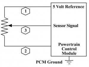
As you can see from this simplified diagram, the MAP sensor works much like any other potentiometer. The potentiometer in a MAP sensor is eqquipped with a diaphram, and connected to a source of manifold pressure. As manifold pressure rises (towards atmospheric, or over in forced induction applications), so does the output voltage. This is caused by the potentiometer moving along the resistor, creating less resistance in the circuit. See below, an oscilloscope pattern we captured by placing the engine under load.
As you can see, we gave the engine short bursts of acceleration. Under a snap acceleration, the voltage from the MAP sensor may reach 4-4.5v. At idle it will sit near .5v, and under acceleration, this will climb with load introduced to the engine. A bad earth, bad connection, etc may cause the MAP to give a false reading. If this reading is too low, it will run the engine lean, and cause a notable lack of power. This is also dangerous to the engine, as running lean can cause problems such as knocks, etc. An unservicable diaphram in a MAP sensor may cause the low manifold pressure to have no effect on the MAP, and this will cause the engine to run rich. You will also feel a lack of power in this instance, and prolonged driving will cause damage such as fouled spark plugs, fouled 0² sensor, fouled CAT converter, among other problems that rich running can cause, including emissions.
The TPS sensor was the next to be tested.
The type of TPS we tested was the more modern Pontentiometer-Type sensor. This type has a contact mounted on the shaft, and a set resistor on which it moves across. At idle, the sensor should show approx. .5v, at WOT (Wide Open Throttle), it should show approx. 4.5v, and anywhere in between while driving. Below is a oscilloscope pattern of a TPS we captured.
In the above picture, we opened the throttle half way, then to WOT, then released it. As you can see, the voltage rises to 2v, then up to around 4v as WOT was applied. Then as we realeased, it dropped back to .5v. A faulty earth or bad connection will cause a lower voltage at the sensor wire, and will cause a laggy throttle response. If the TPS had been removed, or re-adjusted in the past, this may also cause an incorrect voltage.
IAT Sensor
The IAT sensor works with the MAP sensor (Most MAF sensors have IAT's incorporated in their design) to measure the air entering the vehicles intake. At room temperature, the approx. voltage of the IAT is 2.5v, this decreases as the incoming air becomes heated. Below is an Oscilloscope reading of an IAT measuring air as the temperature increases.
The beginning of this pattern shows room temperature. As we applied heat with a heat gun, the temperature rose, and as it did, the voltage dropped to under .5v. The voltage at lower temps is higher, and it is made this way as the air is more dense, therefore richer in oxygen. Therefore, it requires more fuel in the mixture.
The CAS (CAM ANGLE SENSOR) is my final sensor in this segment.
There are numerous types of Cam angle/Crank position sensors that come factory with different vehicles. Toyota's 4A-fe has a CAS built into it's distributor. The 1ZZ has an induction type CPS on the crank. The sensor we tested was on the 1ZZ. Below is an oscilloscope pattern for it.
We used four different functions on a multimeter to find the best one.
DC Volts: 19.5mV
AC Volts: 1.2v
Frq : 0.09kHz
% Duty Cycle: 14.1%


No comments:
Post a Comment