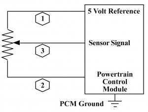
My first task was to wire up a MAP sensor and perform a bench test against manufacture specifications. There are three pin-outs, a 5v reference, an earth wire, and a signal output to the ECU.
After connecting the MAP sensor to a power supply (5v) and my multimeter, i used a Mityvac to apply negative pressure to it, and recorded my outcome. The readings i got adhered to the spec standards of the MAP sensor. This means that the sensor is serviceable and can continue to be used on the vehicle.
There are two variants of MAF sensors. Vane Types, and Hot-Wire Types. The picture below is of a Hot-Wire Type. This type uses a voltage divider circuit containing an electrically heated element (Made of a PTC thermistor) to measure the air flow through its casing.
Unfortunately there were no Hot-Wire Type MAF sensors available to us, so we were unable to perform a bench test on one.
The Vane-Type MAF uses an L shaped plate with a contact, and a resistor much like that of the TPS, to operate. Incoming air forces the plate open, and the contact moves across the resistor, changing the output signal. This type is quite restrictive, as the incoming air must literally force its way through the MAF, reducing flow and effiiciency. It is not used in many modern cars, and has been replaced with the much more efficient Hot-Wire MAF's, and MAP sensors. Below is a picture of a Vane-Type MAF
We wired up a MAF and took readings from our multimeter
at different open positions:
Vane Angle Voltage Out
0° 2.2v
20° 4.7v
40° 6.8v
60° 7.6v
80° 8.1v
100° 8.5v
120° 9.4v


No comments:
Post a Comment